Rebuilt Merchant Navy Class 'Belgian Marine'
Building Two Merchant Navy Locomotives - from notes by the late James Holden.
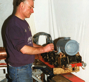
By chance, the Company I was working for went into liquidation, which being honest is the the best thing that could have happened.
So a new business was born, Maiden Precision Engineering, doing work for local firms, whilst allowing me to continue with model engineering, which I was able to do between jobs.
So summer - 1st September 1993 - etched in my mind for all time; the start of an impossible dream that was going to take me 6 years of working in spare time, or 11470 hours - building two Merchant Navy class locomotives.
But no matter how good my engineering, setting up a new business was a difficult time, and it was my father who helped to finance the project and make it feasible.
There is a lot involved in building a Merchant Navy, and building two allows me one to keep, and have one to sell and offset some of the costs.
The materials - steels, bronzes, brass, copper, stainless steel, silver solders, fluxes, gases, fasteners, bolts, nuts, rivets, pins, plus postage and packing all adds up to a very costly engine in its completed form.
Over 14 years later, the M.N. is out the range of most people's pocket and has become unaffordable.
This is why such a high value has been put on the M.N. for sale.
Really, anyone attempting to build this loco should be capable of the engineering involved, but I will explain the difficulties with certain parts of the engine in very broad terms.
Being a skilled engineer I don't think there were any favourite parts, all were done in the way that you were trained, excepting to get a good finish.
The main frames first are straight forward, but the thickness is doubled up at the rear to support the weight of the fire box and cab.
Front buffer beams are o.k., the rear ones are extended with locations for connecting to tender.
The spoons (connections) from the loco to the tender are rods screwed at one end and slotted at the other.
Each of the stretchers and all bracketry for carrying the expansion links, slidebars for the crossheads (in/outside), and screw reverser are fabrications, requiring between 18 and 24 individual pieces.
This was extremely difficult, and I found the best method was to braze using fluxed brass (though careful setting-up is needed first).
Using toolroom machines i.e. lathe plus miller, the 2 outside cylinders and one inside were bored out; M.J. Engineering was asked to quote a price which they did, but recommended me to machine them myself.
While machining the outside cylinders caused no real problems, the inside cylinder was extremely difficult, with an awkward setup as the block is square with bores at an angle of degrees.
This required clamping the block relative to datums for piston and valve angles to bolting face of main frame.
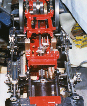
The inside valve guide was badly drawn, made up of bars and spacers in a narrow space, but a M.N. builder in Australia re-designed the cylinder guide for the valve end, although I had only photos to work from.
Wheels and axles are straight forward, quartering of wheels was done using datum centres, slips & gauges.
Coupling rods are not fluted on M.Ns. (only on the West Country class), connecting rods are fluted, as are radius rods; but union links, combination levers, and suspension links are plain.
The expansion links radius was cut using a rotary table; the crosshead is made up of 2 pieces and brazed.
With the front bogie accuracy is needed for the lateral movement on bogie centre.
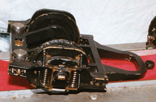
The pony truck is a tricky fabrication as it has to loop over and avoid the axle, with all pieces brazed up.
Axle boxes have roller bearings throughout on the loco and tender.
Leaf springs are made up of 2 of spring steel and the remaining leaves of hard bronze.
The brake assembly has 2 steam actuated pistons for operating brake linkage and hangers.
The buffers are a straight forward turning exercise.
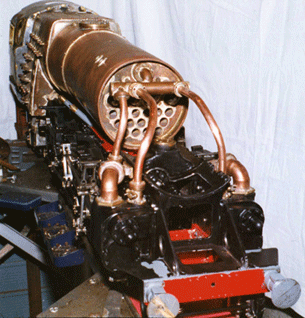
The aluminium casting for the Reverser caused problems as it was too soft, and difficult to hold for machining of the gear housing.
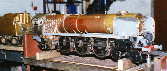
The smoke box was rolled from 1/8" brass sheet and castellated, then s/soldered; door & wind deflectors no problem.
Running boards are quite long and a folder was needed; and on the cab, allow extra length for bends when forming.
I came across a number of errors in the drawings, but in putting this to Keith Wilson, he said to me, "If you've got this far what do you need me for ?"
Then I looked at the locos which were two thirds finished, and thought 'He's right, for all the cock ups I have got this far !'
He also told me this was not a loco he wanted to do, and his words were "I've been shanghaied in to doing the drawings".
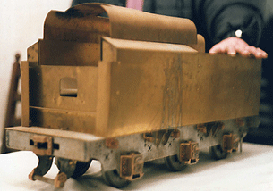
The boiler drawing is wrong for the outer & inner wrappers, too short on overall length, so an extra width of material is needed here.
The combustion chamber is optional, but I decided to incorporate into both M.Ns.
But no real problems in building the boilers, pressure was tested at 180 p.s.i.
The safety valves are a straight forward turning exercise.
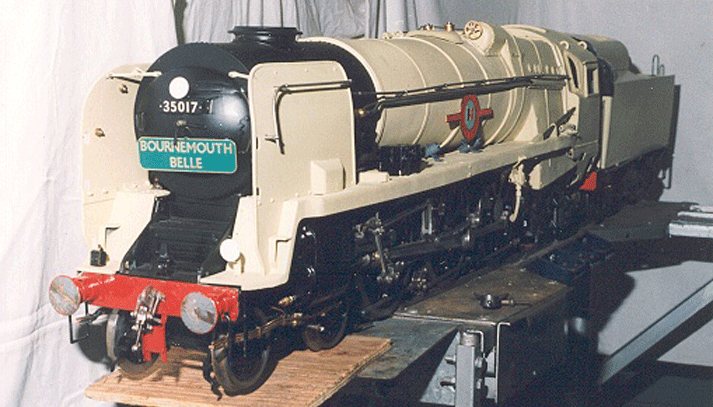
** Editor's note: A full size General Arrangement drawing is now available from M.J. Engineering, drawn by them and issued since the original drawings were published.
The locomotives have been fully completed and painted.