Construction of 5" Merchant Navy 35006
Part 5 of an Article by Kevin Neate
Regulator, Superheater and Firedoor
I decided to work from the back to the front and started with the regulator bits on the backhead.
My boiler has a bush for the regulator rod threaded 5/8” x 26 and I had fitted a pad with four 8BA tapped holes to take the regulator lever bracket.
The KW system as shown is OK but in full size the regulator mechanism on the backhead is contained within a casing, with a gland for the operating rod spindle.
I made the casing from a piece of 1 ¼" brass bar and the bits inside are a lever worked by a square on the operating rod.
This pushes a 5/16" rod through the bush in the backhead and works well.
The casing is screwed onto a flat faced bush with a 5/16" hole on an extension that is screwed into the existing bush in the boiler.
The top section of the backhead is not square to the chassis and slopes slightly – just as well as the regulator mechanism will be obstructed by the cross stays if vertical.
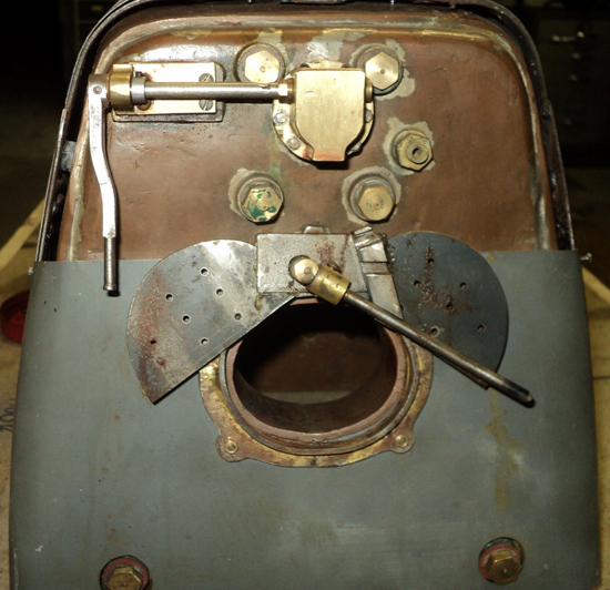
Firehole Door
More or less as per KW using the meccano gears but looking a bit more like the full size with a sprung handle fitting to a notched plate to hold the door.
The firedoor assembly is screwed to the backhead cover plate that is described in the next article.

Regulator
I made the block, sliders and linkages etc for the regulator as per KW without any difficulty and pre-assembled to make sure it works.
The pins for the sliders were peened over so as to make a "cage" assembly held to the regulator block with the pivot screws that I made with oversize hex heads.
My boiler has a front bush for the regulator tube threaded ½" BSP – I cannot recall why I did this !
KW specifies ½" tube to the regulator block.
I have a lot of 9/16" x 1/16" wall copper tube rescued years ago, so I used this instead and threaded one end 9/16" x 26, with a corresponding hole in the regulator block.
At the smokebox end I modified a ½" BSP gas fitting to screw into the boiler bush by drilling through 9/16".
I left the copper pipe overlength for now and free to float in the fitting.
At the regulator end the 5/16" rod fouled on the cross stays.
I cut it off and made a hinged joint onto a length of 3/16" dia brass rod and threaded the other end 3/16" x 40 to fit to the lower slider on the regulator.
So far so good and now the new rod will clear the stays and reach the regulator.
I found the offset bent rod drawn by KW will not work, as it fouls on the boiler tubes if you try to rotate it – the jointed rod still fouls the tubes but only slightly so it will rotate.
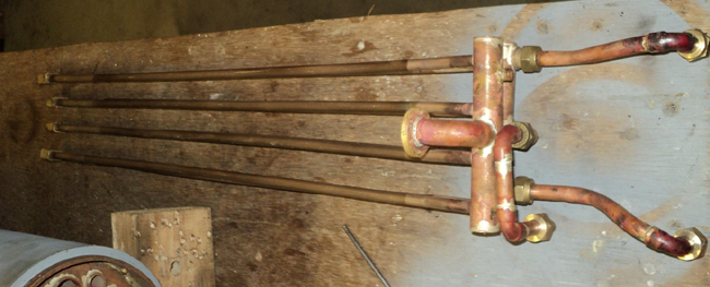
This photo shows the regulator assembly laid out before fitting.
This is the only photo of it I have, and the boiler casing shape is incorrect for 35001–9 but OK for the rest – see next article !
Alas the regulator block will not fit down the hole in the boiler so it has to go in a bit at a time.
The KW article in ME does say fitting the regulator would be difficult and he is right.
It took me a while to work this one out.
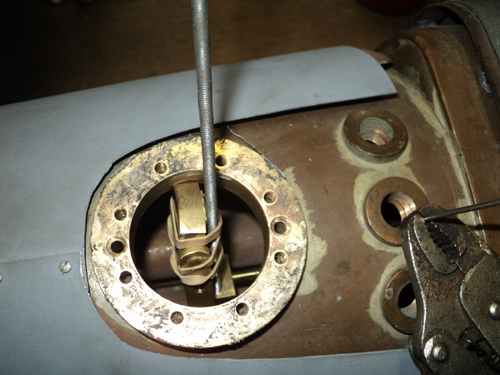
I put a 4BA hole in the lower slider, and by using a piece of 4BA studding this allowed the cage to be lowered into the boiler and engaged with the regulator rod, and screwed up an approximate amount.
I had to put on a temporary piece to stop the top slider falling off.
This assembly is then pulled back so that the regulator block can be dropped in, suspended on wires in the pivot holes and the 9/16" copper pipe screwed home.
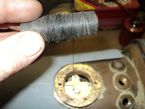
Then wriggle the slider cage over the regulator block and rotate to put in the pivot screws – I tied twine to these in case they dropped into the boiler.
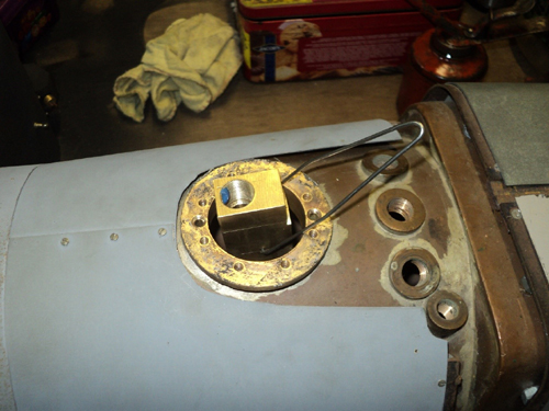
After putting back the operating lever and the regulator housing the whole arrangement worked very nicely, but the regulator block is not yet fixed.
I then used stiff wire on the pivot screws to pull the regulator block up tight to the bush on the boiler and spot through with a 3.7 mm drill.
Now take it all apart again and drill and tap 4BA from the spots.
Then I made two 4BA csk screws from ¼" phosphor bronze rod to hold the block in place.
Success!
Back to the front end I made an olive to fit the 9/16" tube and a modified ½" BSP nut to secure.
Now the front end of the copper pipe has to have a flange to connect to the superheater and this was silver soldered in place.
I finally reassembled the regulator components using Loctite thread sealant.
Easy when you have worked out how to do it!
I just hope it never needs to come apart again.
Superheater
I made the superheater roughly as described by KW to his dimensions with a few deviations!
I bought a coil of 8mm dia x 0.7 wall cupro nickel (Kunifer) fuel pipe.
It is tough stuff, silver solders well, is easy to bend, and from this I made 8 pipes with slight bends each end.
For the front headers I used ¾" dia x 1/16" wall brass pipe.
At the firebox end I made connecting blocks from ¾" x ½" brass drilled in twice at 10 degrees x 9/16" deep to form the returns.
A standard plumbing fitting and brass flange connects the upper header to the regulator tube, with M4 stainless allen screws easily done up with a ball end key.
The return pipes were silver soldered first, then the tube ends were set into the top header that has a hole for the regulator outlet on top which was screwed to the boiler laid upside down.
A 5/16" x 32 nipple is fitted in the upper header to connect the snifting valve - and the whole lot silver soldered in one go.
The idea of fitting the snifter here is to allow air through to cool the superheater when the loco is coasting with the regulator closed.
The lower header was made much the same way using standard 10 mm plumbing fittings to connect with the steam pipes to the cylinders.
The steam pipes were made using 10 mm copper fuel oil pipe - the pipe to the inside cylinder is very close to the superheater, hence the loop to the inlet.
Next is to connect the superheater outlets to the steam pipes in the smokebox.
I used 10mm fuel pipe nuts and olives to connect, all pretty straightforward.
I have various bent spanners that make screwing up the nuts quite easy in awkward spaces.
Snifter and blower
When I made the boiler, I put bushes in for a hollow stay to feed steam to the blower as suggested by KW, 3/8" x 32 at the front and ¼" x 40 on the backhead.
I threaded a length of copper pipe ¼" x 40 and put it in at the front end.
Alas it would not screw into the backhead bush as it was just fouling on the girder stay.
I sorted this out by using 3/16" tube with suitable fittings at each end, and this cleared the stay and worked out OK.
If you want to make your boiler this way, check the location of the hollow stay bushes relative to the girder stay and move the bushes to the right a little bit.
The blower ring connects to the end of the hollow stay deep inside the smokebox, and I found it impossible to do this with the smokebox connected to the boiler so decided to take the superheater out through the smokebox door hole.
Of course it is too wide to come out and it is well nigh impossible to get the three upper screws into the smokebox to connect to the boiler if the superheater is there.
Impasse!
In a previous article I noted that the smokebox is attached to the boiler using six 8 BA screws with rivet heads and using long 8 BA nuts made from 3/16" hex.
For the above work I had put in temporary 8 BA allen screws to hold the smokebox in place.
This is easy when there is no superheater.
I didn't want to cut the superheater headers apart to shorten them.
Instead I moved the top screw three rivets along then made a 3/16" 'socket' from the head of an allen screw welded to a rod.
This allows the nuts to be wriggled into place and turn the rivet head screws into the nuts by hand and slowly tighten.
Very awkward and slow – but possible!!
The snifter is the last bit.
In full size and as per KW, each steam pipe has a snifter valve.
On the MN they cannot be seen as they are hidden by covers.
I did the same here as on the King, and made a single snifter valve connected to the superheater upper header.
I managed to run a 3/16" copper tube through the inside cylinder cavity and out under the LH platform.
If you see steam coming out here you will know the snifter valve is not shutting off when the regulator is opened again.
Safety Valves
My boiler built to the KW design, has the 3 outlet bushes for the safety valves threaded ½" x 26.
The KW safety valve design is good but the drawing is as usual, incomplete !
The innards are fine but the outside shape as shown by KW is not a lot like full size.
Commercial safety valves are available but I am not sure if they will fit.
I experimented with bits of scrap and found that by drilling in at 8 degrees on a circle of 18 holes, 1.8 mm dia and ½" deep I could make a valve body that works the same way as full size.
The ring of holes just breaks into the inner area and will let the steam out.
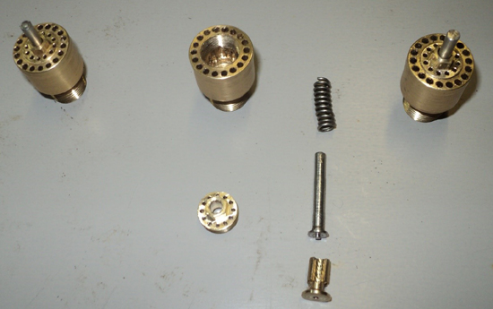
For this to work the valve bore is 10.5 mm which happens to be the tapping size for 7/16" x 40 and the top adjuster was made with this thread and has a ring of 12 holes 3/64" dia, so hopefully the safety valves look something like full size.
Note, the valve spindles in the picture are overlength and will be cut down once the valve pressures are set.